Bale management in Spinning Section – is the process of testing, sorting, and mixing bales according to the properties of fiber for producing the properties of fiber for producing desired quality of yarn at minimum cost in a blow room.

Table of Contents
3 Steps of Bale Management:
- Testing: The samples are collected from 100% bales and tested in HVI (High Volume Instrument)
- Sorting: The bales (sample) are sorted according to mic & tb values. Then, the sorted bales are arranged according to properties.
- Mixing: The mixing plan (lay–down plan) is prepared by maintaining almost the same average mic value in every cross-section. Then, the bales are mixed according to the mixing plan.
Mixing Plan/ Lay Down Plan:
| 1 | 2 | 3 | 4 | 5 | 6 | 7 | 8 | |||||||||||
| 10 | 10 | 9 | 10 | 8 | 9 | 10 | 10 | |||||||||||
| 9 | 9 | 9 | 10 | 10 | 9 | 9 | 10 | 9 | 9 | 9 | 9 | 10 | 10 | 10 | 9 | 9 | 10 | |
| Avg | 9.3 | 9.7 | 9.4 | 9.3 | 8.7 | 9.7 | 9.7 | 9.7 | ||||||||||
| 9.43 | 9.45 | |||||||||||||||||
* The two values show/fall the last row must be equal or close to equal.
Factor Considered for Efficient Bale Management
- 1. Origin
- 2. Length and length uniformity
- 3. Fiber fineness
- 4. Strength and elongation
- 5. SCI (Spinning consistency Index)
- 6. Color
- 7. Trash %
Importance of Bale Management:
- Fiber barre effect is produced if bale management is not used.
- Shade variation occurs in weaving if bale management is not used.
- Color variation occurs in knitted yarn if bale management is not used.
- The variation occurs in knitted yarn if bale management is not used.

Blow-room:
The blow room is the 1st section of the spinning mill, where the bale is turned into a lap by opening, cleaning, and blending or mixing. It is the backbone of the yarn manufacturing process.
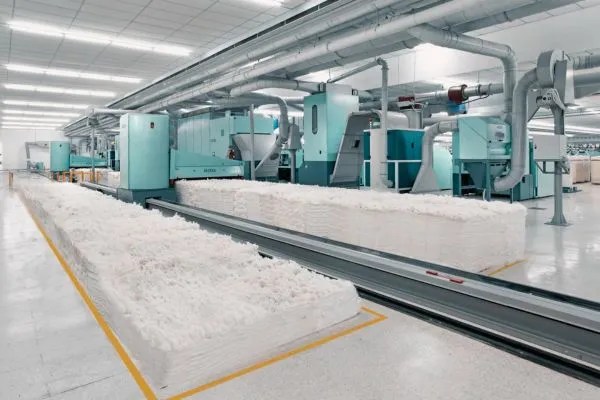
Objectives of blow room:
- To open the fiber tuft.
- Remove dirt, dust, and foreign material from the fiber.
- To produce lap or chute matt.
- To make good yarn.
- To provide a good blend.
Action of Blow room line:
1. Action of opposite spike:
i) Opens the cotton fiber
ii) Reduces the size of cotton tuft
2. Action of Beater:
i) Removes all the impurities
ii) Opens the cotton fiber
3. Action of air current:
i) Moves cotton from one machine to another machine
ii) Separates lint & trash
4. Action of regulating motion:
i) Gives uniform output of cotton fiber.
Basic Parameters to be considered in the blow room:
- No. of opening machine
- Types of beater
- Beater speed
- Types of grid and grid setting
- Amount of grid and grid setting
- Fiber micronaire value
- Temperature and relative humidity
- Position of the machine in the sequence
- Production rate of individual machine
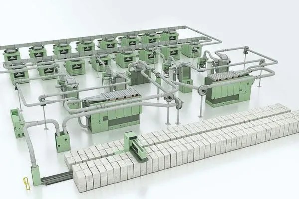
Basic Machinery in blow room line:
- 1. Bale opener
- 2. Pre – cleaner / coarse cleaner
- 3. Mixing machine
- 4. Post cleaner / Fine cleaner
Blow room line of Conventional Machinery:
Bale opener
⬇️
Step cleaner
⬇️
Vertical opener
⬇️
Hopper Feeder – I & II (Mixing machines)
⬇️
Porcupine Opener
⬇️
Scutcher (Post cleaner)
Blow room line of Modern machinery:
1. Blow room line of Reiter:
Unifloc (Bale opener)
⬇️
Argus ( Metal part separator)
⬇️
Uniclean (pre-cleaner)
⬇️
Unimix (mixing machine)
⬇️
Unifies (Post cleaner)
⬇️
Jossi the magic eye (Foreign fiber separator)
⬇️
Condenser (Dust remover)
2. Blown room line of Trutzschler:
Blendomat (bale opener)
⬇️
SP-EM / SP – MF (Metal part separator)
⬇️
CL – P (Pre – Cleaner)
⬇️
Multimixer (Mixing machine)
⬇️
CLC – 3 / CLC – 4 (post cleaner)(cleanomat)
⬇️
SP – FPU / SP – FPO (Foreign fiber separator)
⬇️
Dustex (Dust remover)
Cleaning Machines of Blow room:
1. Step Cleaner:
i) The feed trunk is used for feeding input.
ii) Six beaters are used to remove impurities that are inclined at 45º.
iii) A baffle plate is used to increase cleaning intensity.
iv) A waste box is used to store the impurities.
v) Delivery trunk is used to store the machine output.
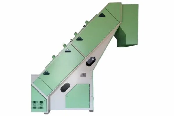
Read More: Step Cleaner in Blow Room with Working Principal
Machine parts of step cleaner are as:
- Feed trunk
- Buffle plate
- Grid
- Waste box
- Delivery trunk
2. Rieter uniclean B12:
i) It has an inlet duct, a cleaning drum, a waste suction device, and an outlet duct.
ii) The tuft is forced to pass over the grid and perforated sheet five times each.
iii) The air suction through the perforated sheet provides very efficient deducting.
iv) The waste is fed to the waste transport via an airlock cylinder, which prevents suitable fibers from being sucked through the grid.

Essential machine parts of Rieter uniclean B12
- Inlet
- Outlet
- waste suction device
- Cleaning drum
- Grid
- Airlock cylinder
Opening Machines of Blow room:
1. Conventional Bale opener:
i) A feed lattice is used for feeding input.
ii) Bottom lattice is used to carry a cotton ball to the inclined spike lattice.
iii) Inclined spike lattice separates cotton balls by upward motion.
iv) A beater and wiper roller is used to remove impurities.
v) An evener roller is used to even cotton.
vi) Swing rod is used as a feed limitation indicator.
vii) Grid is used to separate fiber and impurities.

Machine parts of conventional bale opener:
- Wiper roller
- Evener roller
- Beater
- Striker
- Grid
- Feed lattice
- Bottom lattice
- Inclined spike lattice
2. Rieter Unifloc A 11:
i) A feed duct and two bottom rails are secured to the floor.
ii) A microprocessor is provided for fully automatic material extraction from the bale.
iii) It enables the processing of up to 130 bales.
iv) It can process up to 4 blends.
v) The production rate is up to 1400 kg/hr.

Key Machine parts of Rieter Unifloc A 11:
- Chassis
- control cabinet
- Duct for material transport
- Take off unit
- Bale
Mixing and Blending Machines of Blow room:
Rieter Unimix B 70:
i) It comprises three sections: a storage section, an intermediate chamber, and a delivery section.
ii) Tufts are fed pneumatically and simultaneously into eight chutes.
iii) A conveyor belt feeds the raw material through the intermediate chamber to the feed lattice (spiked).
iv) The material is passed between an inclined spiked lattice and an evener roller.

Machine parts of Rieter Unimix B 70:
- Chut
- Feed chute
- Evener roller
- Delivery chute
- Inclined spiked lattice
Opening unit:
1. Endless path
2. Gripping devices
3. Rotating assemblies
Opening Devices:
1. Spiked lattice:
i) It is used as forwarding and opening devices in bale openers and hopper feeders.
ii) It consists of circulation and an endless lattice with transverse bars of wood or aluminum.
2. Plucking Springs:
i) It is used in modern machines for opening.
ii) It produces mostly large to huge clumps of uneven size.
3. Spiked Roller:
i) It is used in mixing bale openers, step cleaners, etc.
ii) It rotates at 600 – 1000 rpm speed.
Types of Beater:
1. Kirschner Beater:
i) Speed is 800 – 900 rpm
ii) Cleaning efficiency is high
iii) Fiber elimination is high
2. Double pin Beater:
i) Speed is 1100 – 1800 rpm
ii) Better beating action
The operation involved in the blow room:
1. Opening: It is carried out to the stage of flocks in the blow room. Tuft weight can be reduced to about 0.1 mg by opening.
2. Cleaning: Impurities can only be eliminated from the surface of tufts. Blow room removes 40-70 % of the impurities.
i) Cleaning efficiency, CF = (AT – AF )/ AT × 100%
[ AT = Total waste %, AF = Good fibers eliminated %]
ii) Cleaning index, CT = DF – DD/DF × 100%
[DF = Direct content % of feed material, T = Total, DD = Dirt content% of delivered material]
3. Dust removal: The dust particles are completely enclosed within the flocks and, hence, are held back during suction.
4. Even feed of the material: It is necessary to produce a lap of uniform weight per unit length to produce a lap of uniform weight per unit length, or to process a lap of uniform weight per unit or to process the maximum quality, which is suitable for carding.
Principle of Opening and Cleaning in Blow Room:
Principle of opening:
Opening means reducing the size of the tuft to produce individual fiber. Initially, tuft sizes are maximum 10” × 10”. After 3.4 stages of space (manually), the tuft size is about 1” × 1”. But tuft size can be reduced to less than 1” × 1” by using modern machinery.
Principle of cleaning:
Cleaning means the removal of dust and trash material. If the particle size is above 500 πm, it is called dust. Dust and trash are removed in the blow room line by beating the beater and air current.
Factors on which the intensity of opening depends:
1. Raw material:
i) Thickness of feed web
ii) Density of feed web
iii) Fiber coherence
iv) Fiber Alignment
v) Size of flocks in feed
2. Machines:
i) Type of opening device
ii) Speed of opening device
iii) Type of feed
iv) Distance between feed and opening device
v) Degree of penetration
vi) Type of clothing
vii) Point density of clothing
viii) Arrangement of pins, needles and teeth
3. Speed:
i) Throughput speed of material
4. Ambient condition:
i) Relative Humidity – RH %
ii) Temperature
Influencing Factors on Cleaning:
1. Dirt particle
2. Degree of opening
3. Roller speed
Grid in Blowroom:
Types:
1. Slotted sheets
2. Perforated sheets
3. Triangular section
4. Angle bars
5. Blades
Adjustments:
1. Distance of grip from beater
2. Width of the gaps between the bars
3. Setting angle relative to the beater envelope
Influence on cleaning effect via:
1. Section of the bars.
2. Grasping effect of the edges of polygonal bars.
3. Setting the angle of the bars relative to the opening elements.
4. Width of the gaps between the bars.
5. Overall surface area of grid.
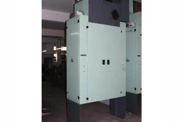
Chute Feed System:
Definition: A chute feed system is a system of feeding small tufts of cotton fibers directly from a blow room to a series of cards.
Advantages:
1. Increases the efficiency
2. Requires less power
3. Avoids the processing of rejected laps
4. Eliminates excessive sliver irregularities
5. Reduces the crushing of foreign materials
6. Extracts trash particles from fibers easily
Disadvantages:
1. Requires more time
2. Not control the medium and long-term variations
3. Produces more waste if mixing is changed
4. Not control the total lap weight
5. Maintenance is not easy
Lap Feed System:
Advantages:
1. Easy maintenance
2. Flexible installation
3. Can reject lap
4. Not require auto levelers
5. Less investment and maintenance cost
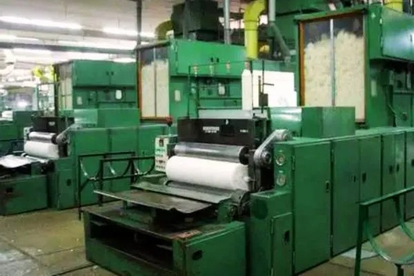
Disadvantages:
1. Needs extra labor for lap transportation.
2. Stops due to lap changes.
3. Loss of more good fibers opening in landing.
4. Creates problems during opening in carding.
5. Irregularity of silver weight.
6. More loads on the taker-in.
Causes and Remedies of Defects in Blow Room:
| Defects | Causes | Remedies |
| 1. Uneven lap | i) Even feed of material) Proper machine maintenance | i) Uneven feed of material) Presence of weak and immature fiber |
| 2. Irregular lap | i) even feed of material) Select mature and strong fiber | i) Less relative humidity) low pressure of calendar roller |
| 3. Soft lap | i) control relative humidity) Required pressure of calendar roller | i) Low pressure of calendar rollers) The low temperature in the blow room section. |
| 4. soft lap | i) Required pressure of calendar roller. ii) Required temperature in bow room section | 6. Holes in the lap |
| 5. dirty lap | i) Improper machine maintenance | i) Proper machine maintenance |
| 6. Holes in lap | Damages cage | Repair cages |
| 7. Conical lap | Dirty cage | Clean cage |
| 8. Licking lap | i) Too much waste ii) Too high fan speed | i) less soft waste ii) Controls fan speed |
Recent Development of Blow Room Line:
1. Improved safety device.
2. Improved input action blend mat/ unifloc (Trutzshler) (Rieter).
3. Electronic / computer-based system for each machine.
4. Better section and management system.
5. Centralized computer control system
6. Different new machines like CVT, CVT3, etc.
Reference:
- https://textiletutorials.com/basic-operations-in-blow-room-section/
- https://textiletutorials.com/basic-operations-in-blow-room-section/
- https://www.slideserve.com/sheshir/spinning-process-powerpoint-ppt-presentation
- https://www.slideshare.net/tanviralamtanvir/tpm-1-97358637
- https://textilestudycenter.com/basic-operations-in-the-blowroom/
- https://www.textileschool.com/122/yarn-formation-spinning/
- https://www.mlvti.ac.in/downloads/Mandator.pdf
- https://www.slideshare.net/88azmir/jute-cotton-blended-yarn-juton
- https://entrepreneursbreak.com/8-common-machine-maintenance-mistakes-and-how-to-avoid-them.html

Mahedi Hasan is a Textile Engineer, as well as a Top Rated content writer at Upwork, a Level 02 Seller at Fiverr, Level 02 Publisher at Ezoic. A passionate textile and fashion content writer, fashion SEO expert, and fashion web designer. Having a B.Sc. in Textile Engineering Degree from Textile Engineering College, Noakhali (TECN). The department is Apparel Engineering. Highly Experienced fashion writer for the last 3+ years. Have extensive 7 years of experience in the wholesale clothing business.
